Converting a Diptrace (or Eagle) Board to Fritzing SVG
Written on March 7th, 2021 by George Beckstein
Converting A Diptrace (or Eagle) Board to Fritzing SVG
Every product needs good documentation! Before trying to sell my TCAN455x Breakout Board, I knew I would need to create a good tutorial.
Fortunately, I learned from the best: Back a few years ago I had a side job writing SparkFun tutorials! Sounds like a dream job, right? It seems so long ago, now, but back in 2015 I started as a contract author for SparkFun (see the content I made here). I was still in college at the time and it made me feel like a “sponsored” nerd :)
“What a sweet gig,” I thought, “receiving free parts and getting paid to play with them!”
And it was fun! From my experience there, I know nothing makes an electronics getting started guide more intuitive (and familiar) than some simple Fritzing diagrams. I have some (partially forgotten) experience with creating custom Fritzing parts in the past, but I also recall it being quite a chore. And then I remembered: “I think there’s a converter script out there.” A little googling and lo-and-behold: eagle2fritzing.
Unfortunately, you will notice the repository hasn’t been touched in a few years and the README specifically states it is not support by Fritzing anymore :)
So I knew installing it wasn’t going to be straightforward.
Installing eagle2fritzing
Since I’m using Ubuntu 20.04, that’s what I will cover installation on. You may find installation on other platforms similar.
I decided to write down these instructions for anyone else since many of the guides are a few years old now and some steps may be outdated!
First, Install Fritzing
I assume if you’re reading this, you’re familiar with Fritzing. It used to be free to download but I had to pay about $10 to get a pre-built copy… I’ll pay to support them because it saves me the headache of building it myself. I have enough poorly documented obsolete builds to perform today.
Anyway, if you’re feeling more adventurous than I, you can download the source for Fritzing here (which you will have to do anyways to build brd2svg later on).
Second, Install Eagle
Since most of the guides for installing eagle2fritzing have been written, Eagle has been acquired by AutoDesk. That’s a really interesting software suite now (I’m a huge fan of Fusion360 already), but that’s for another post. I will say last time I tried Eagle it was very unintuitive. I’m much happier with DipTrace!
Since the eagle2fritzing program uses Eagle during the conversion process, you will need to install it.
Thankfully, Autodesk still allows you to download a non-commercial version here.
Make sure to install it in a directory you’ll remember as you’ll need to have the path to Eagle later, I chose /opt/.
Finally, Install QtCreator
Now, before going further, you will need to download yet another program! To build brd2svg, you will need to install QtCreator. Qt is a popular open-source-ish GUI framework but don’t worry, you won’t need to know very much about it to build brd2svg. You can download it from here.
Build brd2svg
The program we need is brd2svg in the eagle2fritzing repository linked to above. You will have to build it yourself, fun!
Start by making a working directory:
mkdir ~/Documents/fritzing-utils && cd $_
Then, clone both eagle2fritzing and fritzing-app next to each other:
git clone https://github.com/fritzing/fritzing-app.git && git clone https://github.com/fritzing/eagle2fritzing.git`
Once all these steps are done, go ahead and open the brd2svg project in QtCreator:

Unsurprisingly, I encountered a build error right off the bat:
svgfilesplitter.cpp:(.text+0x9834): undefined reference to `DebugDialog::debug(QString, DebugDialog::DebugLevel, QObject*)'
/usr/bin/ld: svgfilesplitter.o: in function `SvgFileSplitter::normalizeAttribute(QDomElement&, char const*, double, double)':
svgfilesplitter.cpp:(.text+0x9c22): undefined reference to `DebugDialog::debug(QString, DebugDialog::DebugLevel, QObject*)'
collect2: error: ld returned 1 exit status
make: *** [Makefile:188: brd2svg] Error 1
I’m not sure if this is a bug, but I have reported the issue here. Luckily, the fix is simple: just comment out the lines referencing DebugDialog::debug.
You may want to change the build profile (bottom left corner of QtCreator), but once you’re ready, just click Build->Build All. The output will be in a new folder, eg: build-brd2svg-Desktop-Debug

Go ahead and copy the brd2svg executable to a place in your path so you can use it by name on the command line, eg: cp build-brd2svg-Desktop-Debug/brd2svg /usr/bin
Now, everything is installed and we’re ready to convert!
Converting a DipTrace Board Design to Fritzing
The first step in converting the DipTrace board design to Fritzing SVG is to actually export the DipTrace board as an Eagle .brd file! Simply open up the design you want to convert and click File->Export->Eagle Board.... Save the exported .brd file and continue to the next step.

Convert the Eagle .brd File to Fritzing
This is where the previously-installed brd2svg utility comes in handy.
First, create a directory to work in: cd ~/Documents && mkdir temp-fritzing && cd temp-fritzing
Now, create another subdirectory called brds: mkdir brds
Copy the .brd file you exported from DipTrace before to the brds subdirectory.
Now, all that’s left is to run the brd2svg utility!
You can read more about the possible command line flags and options here, but suffice to say the command I used was:
brd2svg -w . -e /opt/eagle-9.6.2/eagle -c contrib -a ~/Documents/fritzing/eagle2fritzing/brd2svg/and/
Notice that you’ll have to give the utility the path to your eagle executable and the and subdirectory of brd2svg in the eagle2fritzing repository.
Using Your New Fritzing Parts
Now it’s time to import your converted board into Fritzing!
The tools generated a folder in your working directory, parts. To install the converted part in your Fritzing installation, simply copy the contents of the parts folder into the parts folder in your Fritzing installation directory. On my Ubuntu 20.04 system, this was in ~/Documents/Fritzing/parts.
Don’t mind any warnings about merging folders, the tool deliberately generated files in the same folder hierarchy.
Now, open Fritzing and place your part! I had to actually search all the parts for my TCAN455x Breakout Board.
Hopefully you’ll have better results than I did:
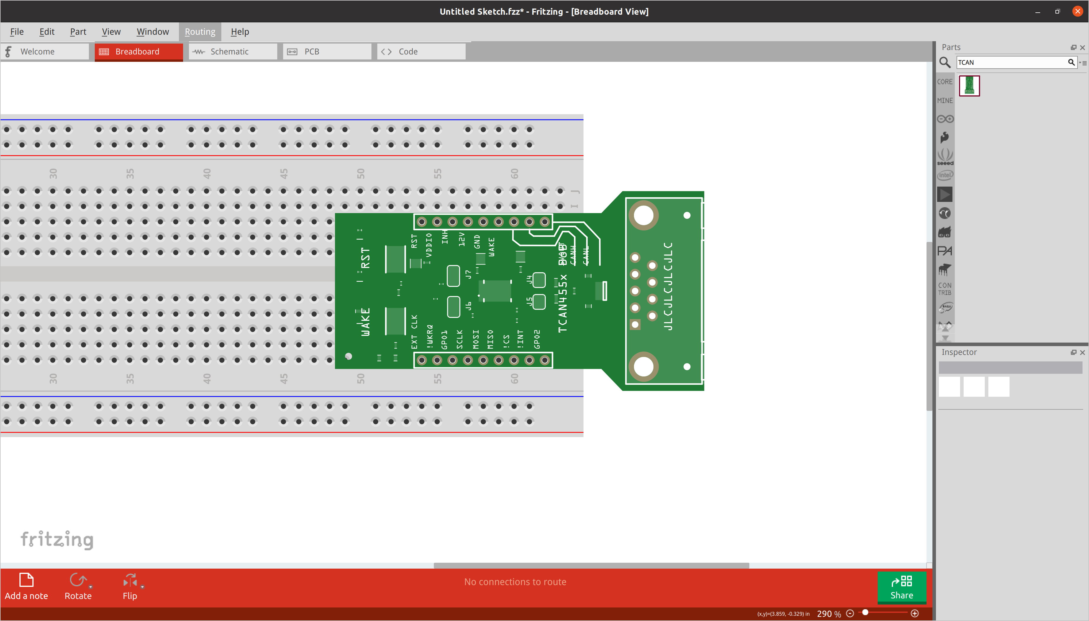 That’s going to require some touching-up
So my design didn’t get converted super well, but it’s at least a start. It saved me a bunch of time trying to recreate the silkscreen, board outline, etc… Just need to add the chips! I’m going to assume the utility relies on common part footprints from the Eagle standard parts library to generate little gray “ICs”.
Oh well, I’ll just add them myself!
Touching Up Generated Output
To fix any visual weirdness in the output of brd2svg, you will need to have a vector graphics editing program. I personally use Inkscape because it’s free and open-source.
Once you have Inkscape or an equivalent program installed, navigate to the parts directory generated by the utility. Then, navigate deeper to find the svg breadboard icon. On my system, this was in parts/svg/contrib/breadboard. You can also modify the schematic symbols and PCB layers if necessary.
Once open in your vector graphics tool, you can start modifying the generated svg files!
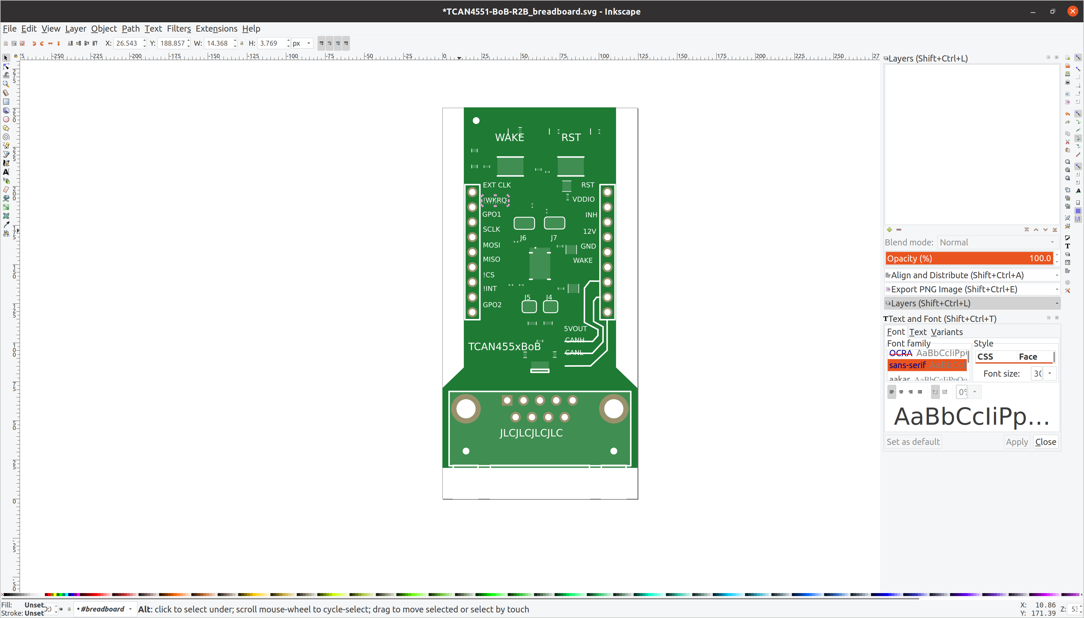
I had to ungroup the elements of the SVG to be able to modify them individually.
The first thing I did was clean up the silk screen as some of the text was offset:
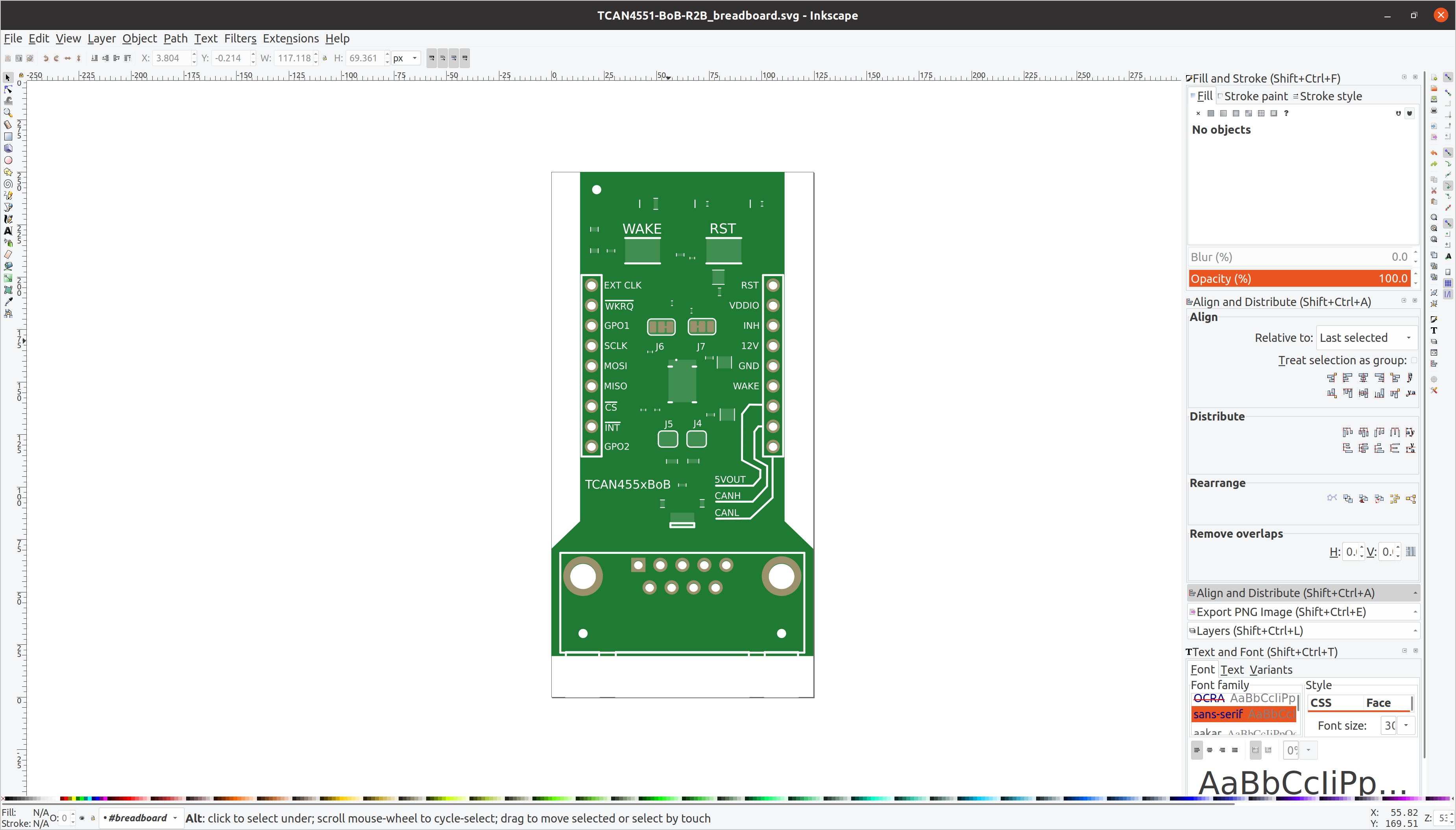
Adding Components
Fritzing ships with a bunch of component icons in SVG format, you just have to find them! After looking at the install script, I found that on my system Fritzing installed to /usr/share/fritzing.
What I did from here was find an existing Fritzing part that has a similar component on it. Then, you search for that part’s SVG file in /usr/share/fritzing/fritzing-parts/svg/core/breadboard:
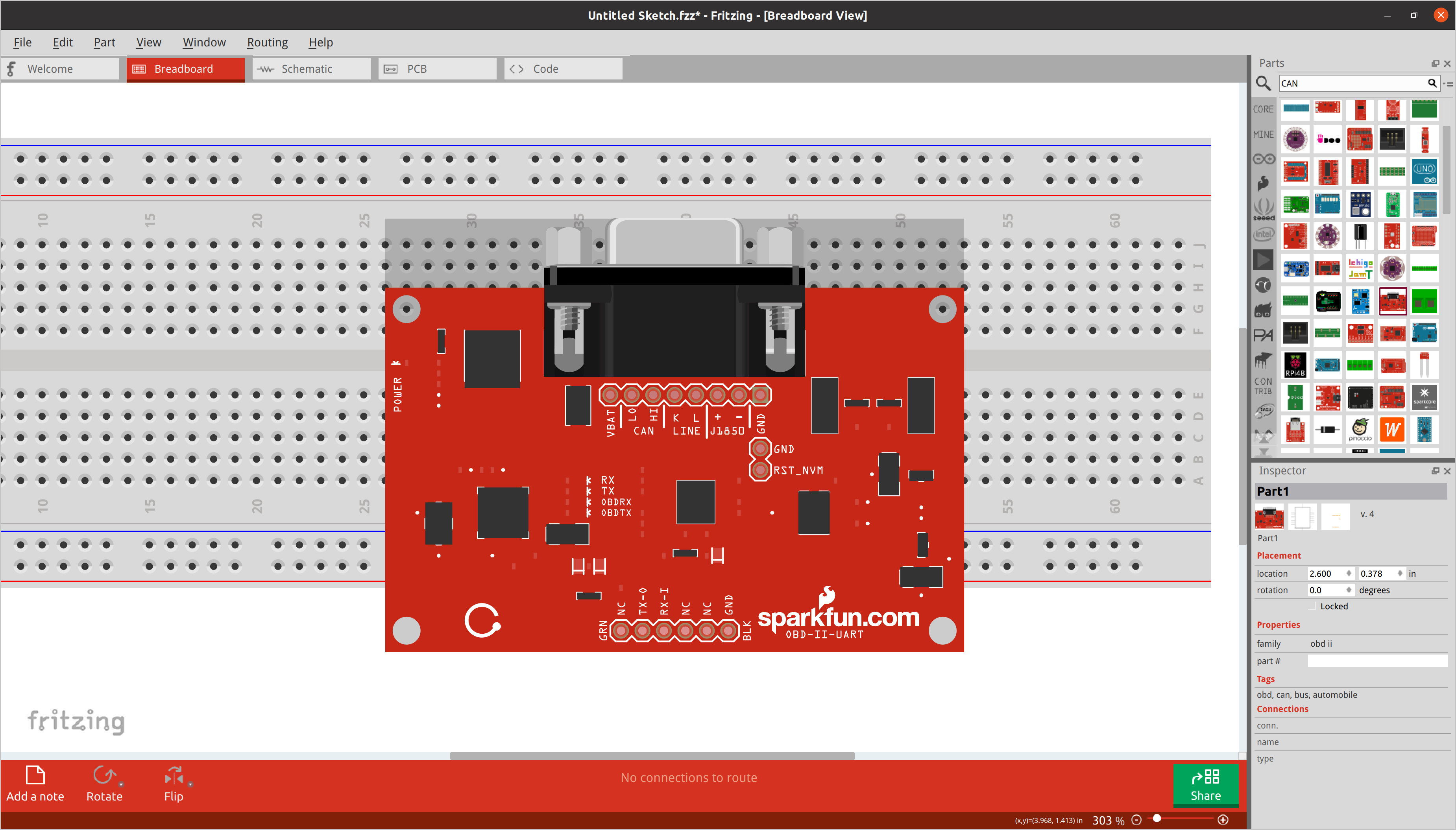 `The DE9 connector on this SparkFun OBD2-to-UART board should work nicely on my TCAN455x BoB
After a bit of searching, I found most of the parts I needed and just created the passives out of rectangles.
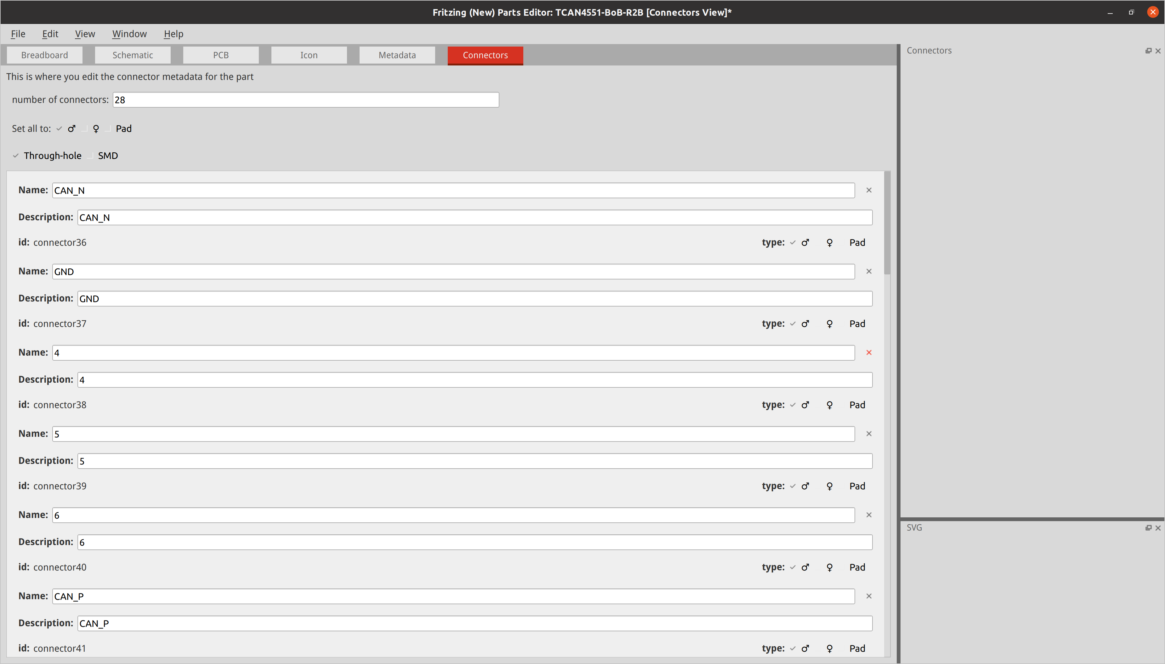
Fixing Extra Pads and Other Glitches
The last step is to fix any glitches in Fritzing itself. I can’t recall how Fritzing identifies pads that can be wired to, but I have a feeling maybe its some metadata or even the color of the vector shape. Regardless, my converted Fritzing part had some extra pads I needed to get rid of.
To do this, open Fritzing after installing your new part as above. Then, place your part in the breadboard view, right click it, and then click Edit (new parts editor).
This will open up the Fritzing parts editor. In the right pane, you will see a list of wire-able pads.
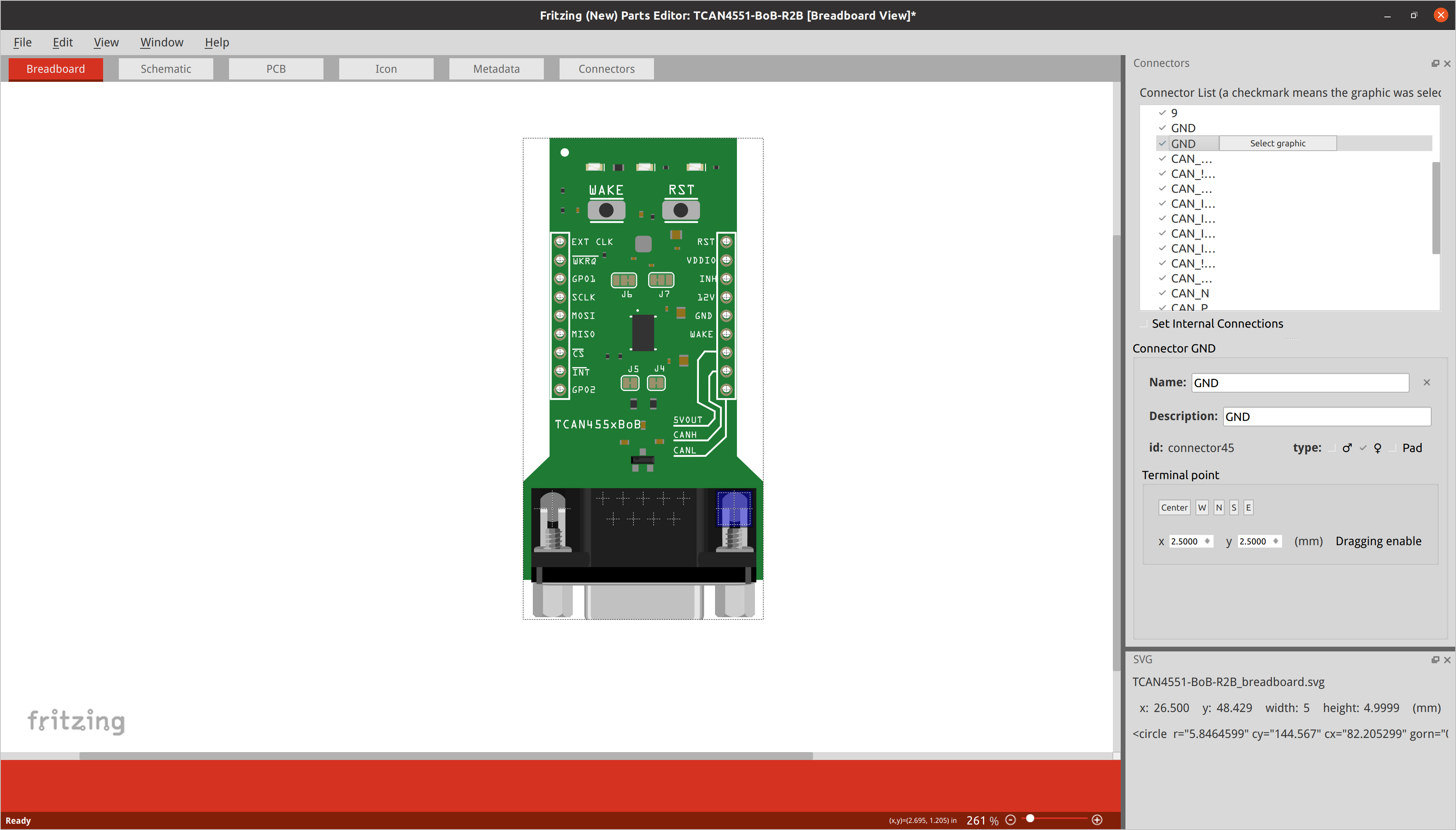
To delete the ones you don’t want, go to the Connectors tab and click the little “X” in the undesired connector’s box:
After a bit of work, our custom Fritzing part is ready!
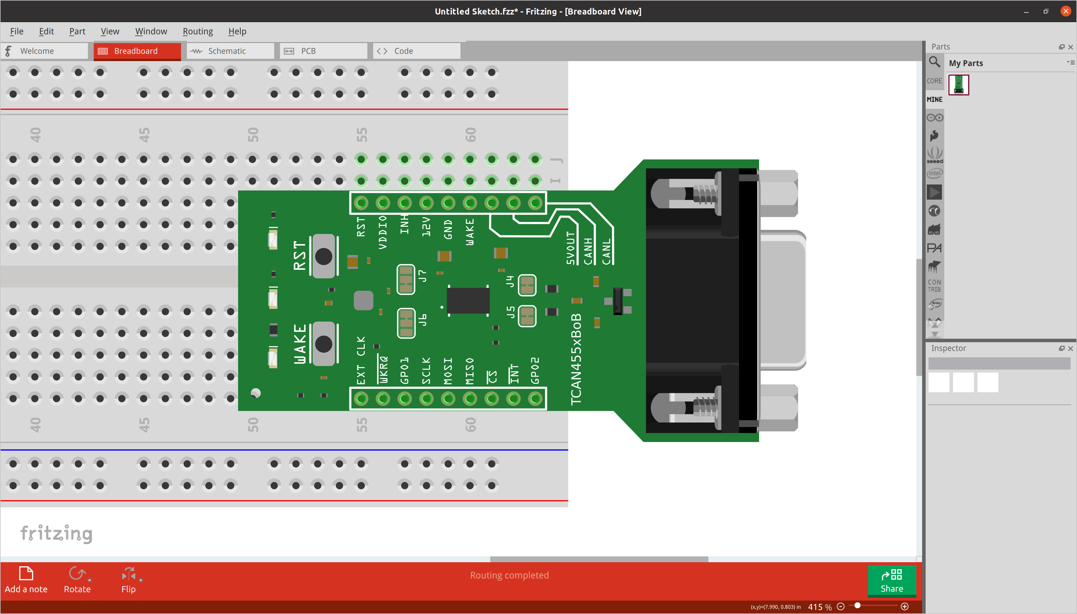 et voila!
I didn’t say it was going to be easy… but here we are, we have gone from DipTrace PCB design to Fritzing part. Now that I have this written down, I hope it will go faster the next time I have to do it :)
References and Going Further
Here are a few related web pages I referred to when doing this myself and writing this post: