Getting Started with the TCAN455x Breakout Board
Written on May 4th, 2021 by George Beckstein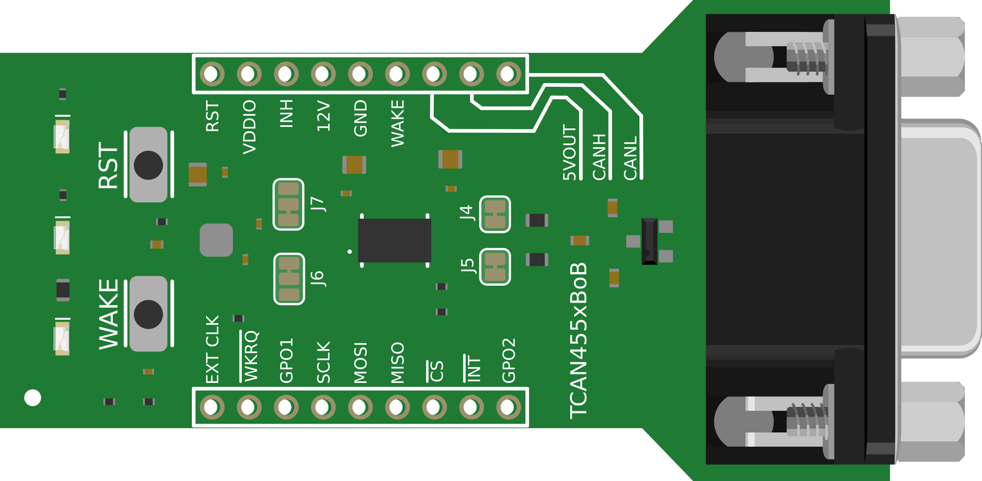
Getting Started with the TCAN455x Breakout Board
Introduction
The Shack on Wheels has a number of custom electronic modules planned, from tire pressure monitoring to an accelerometer-driven auto-leveling system for the air suspension, there’s sure to be a lot of electrons flying around. What good is all this data without a way to share it between modules for feedback, or display critical information to the driver?
And no, I’m not talking about a really long USB cable or something.
Since the computerization of vehicles around the 1980s, every vehicle manufacturer has faced this same problem.
Fortunately, they have also solved it in a number of ways. One of them being the CAN bus. I won’t go into details on how the CAN bus works – that has been covered ad nauseam – but suffice to say it is a robust and reliable hardwired networking protocol that has widespread adoption in a number of industries, especially automotive.
This popularity has landed dedicated CAN bus controllers in a variety of microcontroller product lines, such as certain variants of the venerable STM32 family. That being said, CAN is considered primarily an industrial protocol and tends to add a price premium to whatever device it is integrated into.
This means that a majority of microcontrollers out there, whether low-cost or consumer electronics-oriented, don’t have an integrated CAN peripheral.
What does one do if their favorite MCU doesn’t have CAN?
That’s where chips like the TCAN455x come in!
TCAN455x: CAN Controller and Transceiver
The TCAN455x, released in 2019, is a relatively new product from Texas Instruments. It integrates a lot of functionality all into one little, cost-effective chip.
The TCAN455x is marketed as an “SBC”, or “System Basis Chip” by TI. Whatever marketing term they want to use:
Essentially, the TCAN455x is a SPI-connected CAN controller and transceiver along with some extra features and a nice price tag to boot – sub $1 @ 1k quantities.
 Courtesy of Texas Instruments
Why do I say that the TCAN455x is a CAN controller and transciever?
In a typical CAN system, each node in the network has a controller where all the protocol logic is. The transceiver is a relatively dumb device that simply turns the single-ended output of the CAN controller into the differential signaling that makes CAN so reliable (if you’re not sure what these terms mean, don’t worry, check out this link).
Normally, these two devices are split into separate chips. The STM32 that has a CAN peripheral integrates just the CAN controller. You still have to have an external transceiver to participate on a CAN bus.

What makes the TCAN455x so special, and the reason I chose it as my go-to for enabling CAN-bus for the CAN-less, is that it integrates both into the same package. This saves both board space and cost.
Extra Features
Not only that, but the TCAN455x has a few other nifty features:
CAN-FD
It supports the latest CAN-FD (Flexible Datarate) standard, which extends the CAN packet payload from 8 bytes to 64 bytes. It also allows the data payload to be transmitted at up to 8Mbps, 8 times faster than classic CAN’s maximum of 1Mbps!
Since CAN-FD is the latest CAN protocol, you can be sure your design isn’t going to be obsolete very soon.

Backwards compatible with CAN 2.0A/B
In addition to supporting CAN-FD, the TCAN455x is backwards compatible with CAN2.0A and B. This means that the TCAN455x can operate on a bus using both standard (11-bit) identifiers and extended (29-bit) identifiers.
Built-in automotive grade LDO
On the TCAN4550 variant, the chip also embeds an automotive-grade, wide-input range LDO that can supply up to 70mA at 5V to your external circuitry! That’s more than enough to power a microcontroller.
This is actually one of the more useful features of this chip. Anything taking power off the 12V battery bus in a vehicle must be fault-tolerant and able to withstand load dump voltages of around 40V. Not only that, but your off-battery power system must also be able to operate with an extremely low dropout to keep the system from browning out during cold cranking when the 12V line can drop to 6V or lower!
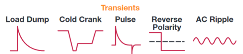 Courtesy of Analog Devices
These features in an LDO or DC/DC converter command high premiums.
The TCAN4550 simplifies all of this, again saving cost and board space. Neat huh?
Other features
Aside from the main features above, the TCAN455x series of chips has built-in diagnostics available over SPI and a number of fail-safe features.
Additionally, the TCAN4550 integrates a watchdog timer that can be used as an additional fail-safe in your automotive system.
Before We Start
There’s a few things you’ll need before we start.
Required Materials
- An Mbed-OS target. I will be using the nRF52832DK in this guide.
- Two TCAN455x Breakout Boards (or one and a CAN bus device you want to communicate with)
- A female to female DB9 serial cable (or you can just use jumper wires)
- An assortment of jumper wires
- A breadboard
- Soldering iron and supplies
Suggested Reading
- If you haven’t worked with Mbed-OS before, you should check out the quick start guide here!
- Learn all about regular CAN bus here
- Learn about CAN-FD here
Hardware Overview
Before we dive into the hardware, you will need to solder male header pins onto the TCAN455x BoB. My favorite method is to place the headers into a breadboard, place the board you’re soldering them to on top of the pins, and then solder away. The breadboard helps hold the headers in alignment so your board is easy to install/remove.
Once that’s finished, you’ll end up with something that looks a lot like the following:
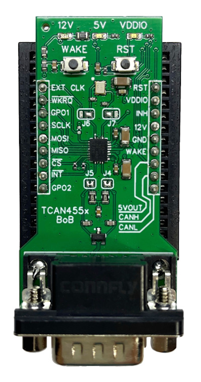
From the top down:
Power Status LEDs
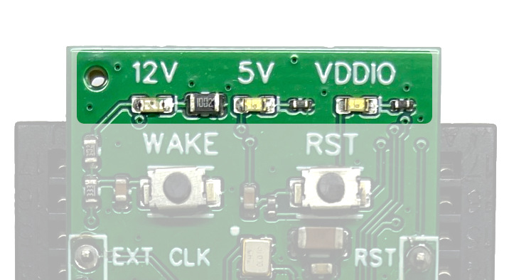
At the top of the board we find three LEDs. These LEDs will be lit if the corresponding power domain has power going to it.
12V LED
The 12V LED will be lit if there is a voltage present on the 12V pin of the break out board. While it’s labeled “12V”, the TCAN4550 will operate with supply supply voltages down to 5.5V. It can also opreate normally up to 30V, and tolerates transient surges up to 42V. The LED circuit has been designed with this operating voltage in mind, so you won’t blow out any LEDs if you use the TCAN455x-BoB in a 24V system.
5V LED
As mentioned earlier, the TCAN4550 has an internal LDO that you can pull up to 70mA from to power external circuitry (note: the TCAN4551 variant does not claim to allow you to draw any current from the internal 5V LDO). The LED labeled 5V indicates if the TCAN455x’s internal LDO is enabled.
The 5V LDO is disabled when the TCAN455x is in sleep mode. Sleep mode is normally entered explicitly by commanding it over the TCAN455x’s SPI interface. There is also a fail-safe mode where if the TCAN455x remains unconfigured at power on (ie: the host microcontroller is stuck or something), it will automtically enter sleep mode after a certain timeout. This is important to note: If you reset the TCAN455x and don’t configure it, it will power down due to this failsafe! If the rest of your system is powered by the TCAN’s 5V LDO, you must always reinitiliaze the TCAN455x after resetting it!
VDDIO
Another nice feature of the TCAN455x is that it supports 5V and 3.3V operation, making it compatible with the newer generation of 3.3V microcontrollers and backwards compatible with 5V Arduinos and such. The VDDIO pin provides a reference to the TCAN455x so it knows whether it should accept logic levels at 5V or 3.3V. The VDDIO LED will be lit when this voltage is present.
Wake and Reset Buttons
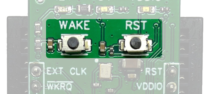
Below the LEDs are two buttons: WAKE and RST.
WAKE Button
The WAKE button pulls the TCAN455x’s WAKE pin low. A low or high pulse on the WAKE pin will wake the TCAN455x from sleep mode, enabling the internal 5V LDO.
RST Button
The RST (for reset) pulls the TCAN455x’s reset pin up to VDDIO (note: the TCAN455x reset pin is active high, in contrast to the active low configuration commonly seen in ARM microcontrollers).
This resets the TCAN455x and will also wake it out of sleep mode. All of the internal registers will be reset to default and the TCAN will start the failsafe timer until it is configured by the host miicrocontroller.
40MHz Crystal and Jumpers J6 and J7
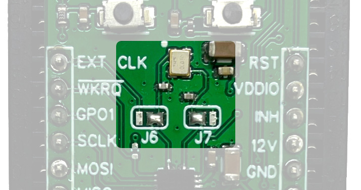
Moving along down the board we come to a 40MHz crystal oscillator and two solder jumpers, J6 and J7. To communicate at high bit rates up to 8Mbps on the CAN bus, the TCAN455x requires an accurate time reference. That’s what the 40MHz crystal is for, it generates a highly stable and accurate 40MHz reference.
To save on BOM costs, you can provide an external digital clock signal. To use this feature, cut the trace connecting the two innermost pads of both J6 and J7, then solder both J6 and J7 so the outside two pads are bridged. This connects J7 to ground, telling the TCAN it should configure itself to use the external clock signal. J6 connects the TCAN’s OSC1 pin to the breadboard pin labeled “EXT CLK”. This is where you would connect your external clock source.
TCAN455x and Breakout Headers
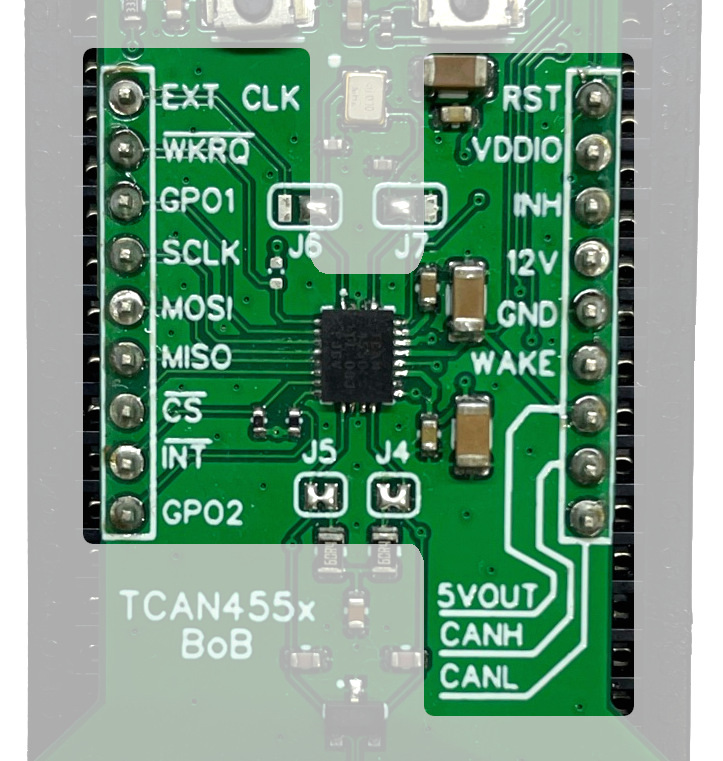
Next, we have the TCAN455x itself, along with its supporting decoupling capacitors and pull-up/pull-down resistors. The breakout headers straddle each side of the TCAN455x and allow you access to every pin on the TCAN. I will explain later what each pin is for.
Termination Network, J4, and J5, and the DE9 Connector
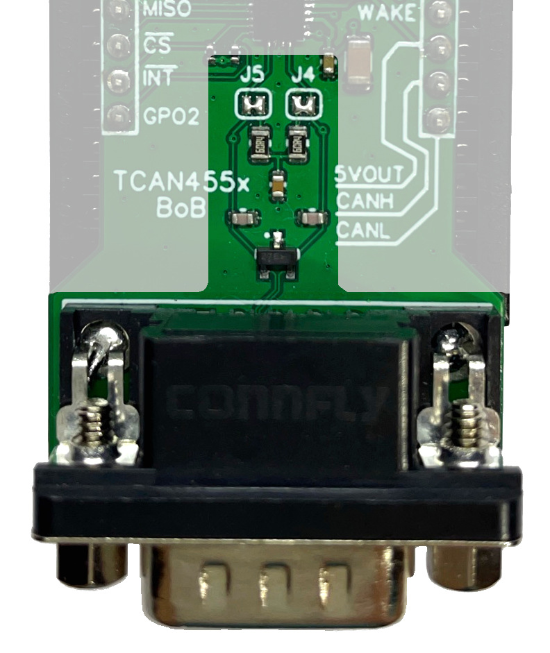
Lastly, at the bottom of the board, we have an optional split termination network, the configuration jumpers J4 and J5, along with the DE9 connector.
The CAN bus protocol requires a termination network at the end of each bus to enhance signal integrity. By default, the termination network is included in the CAN output of the TCAN455x-BoB. If you are using the TCAN455x in the middle of your CAN bus, you can disable the termination network by cutting the small trace on both J4 and J5.
Hardware Hookup
The TCAN455x is controlled over SPI but there are a few extra signals that are needed. The SPI bus required four signals: MOSI, MISO, SCK, and CS. In addition to these, the Mbed-OS TCAN driver requires an interrupt input pin connected to the TCAN’s INT pin.
Optionally, an MCU GPIO can be connected to the TCAN’s RST pin to be able to reset the TCAN through hardware. The driver also has an option that lets you manually pull the WAKE pin high or low, but this requires an external pull-up/pull-down transistor (the WAKE pin is a high voltage input and cannot be connected directly to the MCU GPIO).
Depending on your target, you will have to hook up the pins differently. On my target (nRF52832DK), any pin can be an interrupt input or SPI pin. Some targets, like STM, have specific pins for each peripheral.
If you’re also using the nRF52832DK, you can run my example program (covered in the next section) directly if you hook up the pins the same as below:
There’s two tables because we’re using two TCAN455x-BoBs for this demo (loopback test), but you can only hook up the first one if you have a CAN device you want to listen to already!
First TCAN455x-BoB Pin Hookups
| TCAN455x Pin | nRF52832DK Pin | Other Target |
|---|---|---|
| SCLK | P0.30 | SPI SCLK Capable Pin |
| MOSI | P0.29 | SPI MOSI Capable Pin |
| MISO | P0.28 | SPI MISO Capable Pin |
| CS | P0.04 | SPI CS Capable Pin |
| INT | P0.03 (A0) | Interrupt Capable Pin |
| RST | P0.31 | GPIO Pin |
| VDDIO | VDD | Logic Supply Voltage |
| GND | GND | Ground |
| 12V | 5.5V-30V Source | 5.5V-30V Source |
Second TCAN455x-BoB Pin Hookups (optional)
| TCAN455x Pin | nRF52832DK Pin | Other Target |
|---|---|---|
| SCLK | P0.27 | SPI SCLK Capable Pin |
| MOSI | P0.26 | SPI MOSI Capable Pin |
| MISO | P0.02 | SPI MISO Capable Pin |
| CS | P0.25 | SPI CS Capable Pin |
| INT | P0.24 | Interrupt Capable Pin |
| RST | P0.23 | GPIO Pin |
| VDDIO | VDD | Logic Supply Voltage |
| GND | GND | Ground |
| 12V | 5.5V-30V Source | 5.5V-30V Source |
If you don’t have an adjustable power supply, you can use a 9V battery as the input to the TCAN455x-BoB 12V pin.
These connections are illustrated in the Fritzing diagram below:
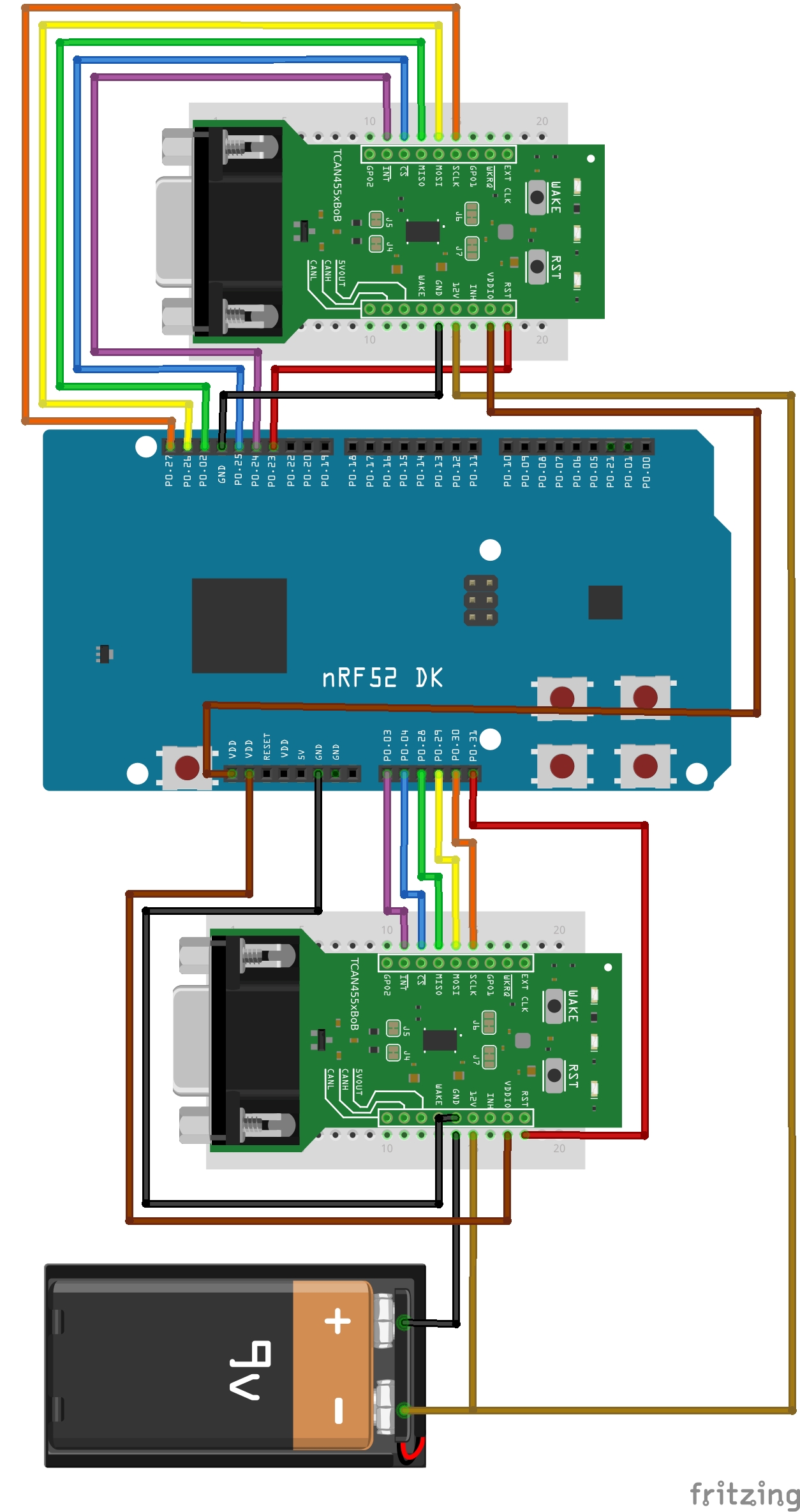 Right click the picture and click “View Image” to enlarge the image
It’s not shown in the Fritzing diagram, but use the female-to-female DE9 cable to connect the boards together. If you don’t have one, don’t worry, a pair of jumper wires connecting the TCAN455x-BoBs’ CANH and CANL pins will also work.
Mbed-OS Library
To make your life easier, I have already written an open-source TCAN455x driver for Mbed-OS! I will not go over how to get started with Mbed (see resources linked to above), but you can download my example program from this repository.
Simply clone the example program:
git clone git@github.com:AGlass0fMilk/tcan455x-bob-gsg-example.git
Change directories into the newly created repository: cd tcan455x-bob-gsg-example
Then, use Mbed’s tools to download the dependency libraries:
mbed config root . && mbed deploy
Note: At time of writing, this example uses a branch on my fork of Mbed-OS because the feature is not yet merged into mbed-os mainstream. This branch enables polymorphism of the Mbed CAN driver. This allows you to use the TCAN455x driver as if it were a native CAN object! This means any existing code written for Mbed’s native CAN driver will work out of the box with the TCAN455x driver! Also note that this feature is still experimental, and requires you to add the FEATURE_EXPERIMENTAL_API to your target. This is done by the following line in the example’s mbed_app.json:
"target.features_add": ["EXPERIMENTAL_API"]
Now you can build the example for your target (using Mbed CLI1, does not yet support CLI2/cmake): mbed compile
Once the build is done, flash your target! If you have everything hooked up right, you should see debug output on the terminal similar to the following:
TCAN455x BoB Getting Started Guide Example
message sent: 1
message received: 0
message sent: 2
message received: 1
message sent: 3
message received: 2
message sent: 4
message received: 3
message sent: 5
message received: 4
message sent: 6
message received: 5
LED1 and LED2 should be blinking at the same time as well.
That’s it, you’re ready to use the TCAN455x in your project! Just make sure to hook up the pins in a similar manner.
If you find a bug or improvement for the driver, please submit an issue on GitHub, or even better submit a pull request!